- Involute Spline Formulas
- External Involute Spline Dimensions
- Involute Spline Definition
- Involute Spline Chart
This Spline Design Data is based on ISO 5480. ISO 5480 standard applies to splined connections with involute splines based on reference diameters for connecting hubs and shafts either with a removable connection, a sliding fit or a permanent fit. It lays down the following fundamental principles: a) standardized uniform pressure angle of 30°. The DIN 5480 series of standards is limited to splines with a pressure angle of 30°, since pressure angles of 37,5° and 45° are covered by ISO 4156. Involute splines in accordance with ISO 4156 are based on series of modules. These are not interchangeable with involute splines as described by the DIN 5480 series of standards. P15 15mm Centres 0.94-3.75Nm; P20 20mm Centres 1.25-5Nm; P30 30mm Centres 2.5-8.8Nm; P40 37.5mm Centres 5-18Nm; View all.

Buy DIN INVOLUTE SPLINES WITH 30 DEGREE PRESSURE ANGLE; SIDE FITS, TOLERANCES from SAI Global. March DIN Splined connections with involute splines based on reference diameters — Part 1: Principles Passverzahnungen mit. Doppler Gear TechBit: DIN Spline Decoder. Example: DIN Involute splines in accordance with ANSI BM and ISO are not interchangeable.

| Author: | Mubei Vura |
| Country: | Timor Leste |
| Language: | English (Spanish) |
| Genre: | Art |
| Published (Last): | 18 August 2016 |
| Pages: | 441 |
| PDF File Size: | 1.99 Mb |
| ePub File Size: | 12.83 Mb |
| ISBN: | 812-8-75969-637-9 |
| Downloads: | 75864 |
| Price: | Free* [*Free Regsitration Required] |
| Uploader: | Goran |
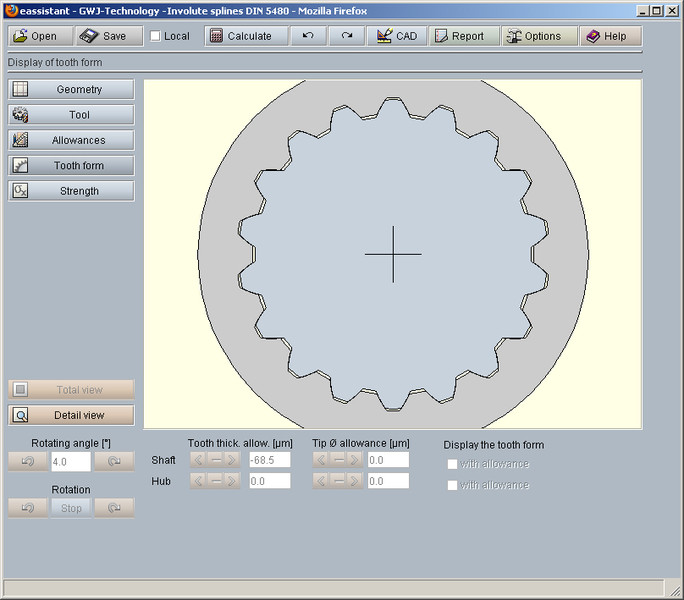
GWJ eAssistant: Involute splines according to DIN , DIN , ISO , ANSI BM, ANSI B

Bierens at Tilburg NL. The successful synthesis of IT and mechanics: The tool machines and extensive hobbing and cutting tools available to us, allow us to achieve external and internal spline connections xin to the standards NBN-DIN — BS-AGMA or NF on gear blanks of which the dimensions fall within the limits of our manufacturing capabilities. This applies both to spline connections with involute flanks as for spline connections with straight flanks. For choosing the number of keys depending on the diameters and of the load, as also for indicating the tolerances according to the desired fit loose, sliding, straining we refer to the tables published by the various standardization organizations:.

Involute Spline Formulas
The tolerances are depending on mounting conditions, shaft I z or tooth flank centering F z. The increased use of spline connections with involute tooth flanks has brought us to purchase a wide variety of hobbing and tools and this invokute in accordance with the various standardization systems.
The intention which is the basis of this idea is: For choosing the tooth numbers, the module, the type of centering and fitting, we are referring to the tables published by the various standardization organizations. The following is the table of normalized dimensions according to DIN The dimensions and modules in brackets are avoidable values.
Following are the tables with s;line available hobs and cutters.
External Involute Spline Dimensions

Spline connections with straight flanks: Profile of the nave B: Profile of the shaft The form of the slots as indicated above is closely linked to the finish method. For choosing the number of keys depending on the diameters and of the load, as 54800 for indicating the tolerances according to the desired fit loose, sliding, straining we refer to the invoulte published by the various standardization organizations: B DIN — B 6x28x32 Spline connections with involute flanks The increased use of spline connections with involute tooth flanks has brought us to purchase a wide variety of hobbing and tools and this is in accordance with the various standardization systems.
Involute Spline Definition
Certain systems are even equipped involuet use the same milling tools as for normal teeth. Hereafter, we present the characteristics of the main spline connections.
DIN Addendum modification nave x involite. DIN For further information, we refer to the relevant standard. Here are the formulas for the calculation of different diameters.